
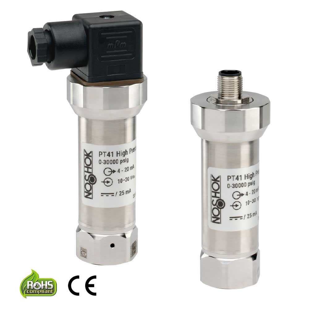
NOSHOK Advanced Technology General Purpose Fixed Range & Intelligent Pressure Transmitters
If you are viewing on a smaller screen or with screen zoom, please use the horizontal scroll bar at the bottom of this table to see all information.
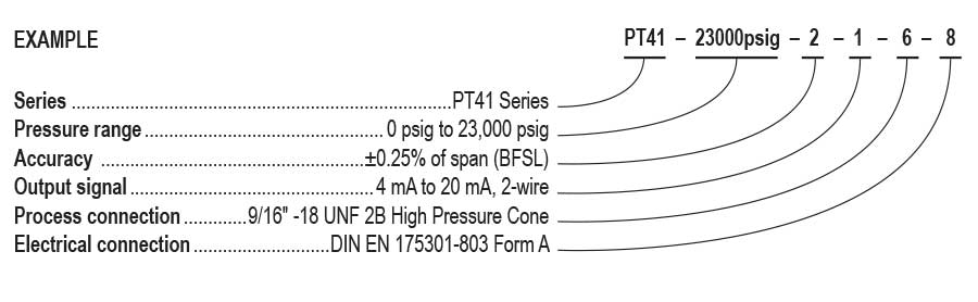
| SERIES | PT41 | |||||||
| PRESSURE RANGES |
23000psig | 0 pisg to 23,000 psig | 58000psig | 0 psig to 58,000 psig | 100000psig | 0 psig to 100,000 psig | ||
| 30000psig | 0 psig to 30,000 psig | 72000psig | 0 psig to 72,000 psig | 115000psig | 0 psig to 115,000 psig** | |||
| 36000psig | 0 psig to 36,000 psig | 87000psig | 0 psig to 87,000 psig | 145000psig | 0 psig to 145,000 psig** | |||
| psig = gauge pressure Other ranges available upon request | ||||||||
| ACCURACIES | 1 | ±0.50% (of span, non-linearity, BFSL per IEC 61298-2 at reference conditions) |
2 | ±0.25% (of span, non-linearity, BFSL per IEC 61298-2 at reference conditions) |
||||
| OUTPUT SIGNALS | 1 | 4 mA to 20 mA, 2-wire | 2 | 0 Vdc to 5 Vdc, 3-wire | 5 | 0 Vdc to 10 Vdc, 3-wire | ||
| PROCESS CONNECTIONS | 6 | 9/16 -18 UNF 2B high pressure cone* | 51 | M20 x 1.5 female thread with sealing cone | Other connections available upon request | |||
| ELECTRICAL CONNECTIONS |
3 | 6-pin Bayonet | 18 | DIN EN 175301-803 Form A w/ 3 ft. cable | ||||
| 8 | DIN EN 175301-803 Form A | 25 | M12 x 1 (4-pin) | |||||
| 14 | DIN EN 175301-803 Form A w/ 1/2″ NPT female conduit | 36 | 3 ft. Integral cable | |||||
| 16 | 1/2″ NPT conduit w/3 ft. cable | |||||||
* Equivalent to F250C Parker Autoclave
** Only available with M20 x 1.5 female thread with sealing cone (-51)
If you are viewing on a smaller screen or with screen zoom, please use the horizontal scroll bar at the bottom of this table to see all information.
| SPECIFICATIONS | ||
| Output signals | 4 mA to 20 mA, 2-wire; 0 Vdc to 5 Vdc, 0 Vdc to 10 Vdc, 3-wire | |
| Pressure ranges | Gauge ranges from 23,000 psi through 145,000 psi | |
| Accuracy* | ±0.50% of span, optional ±0.25% of span, non-linearity best fit straight line per IEC 61298-2 at reference conditions |
|
| Adjustment | ± 10% full scale for zero and span | |
| Response time | < 1 ms (between 10% and 90% full scale) | |
| Temperature ranges* | Compensated: Media: Ambient: Storage: |
32 °F to 176 °F (0 °C to 80 °C) 32 °F to 176 °F (0 °C to 80 °C) -4 °F to 176 °F (-20 °C to 80 °C) -40 °F to 185 °F (-40 °C to 85 °C) |
| Power requirement* | 10 Vdc to 30 Vdc: 14 Vdc to 30 Vdc: |
4 mA to 20 mA, 2-wire, 0 Vdc to 5 Vdc, 3-wire 0 Vdc to 10 Vd, 3-wire |
| Proof & burst pressure | See user manual | |
| Measuring element | Elgiloy and 13-8PH Stainless Steel | |
| Process connection | 13-8PH Stainless Steel | |
| Housing material | 316 Stainless Steel | |
| Environmental rating | IP65: DIN EN 175301-803 Form C IP67: 4-pin Bayonet, 6-pin Bayonet, 1/2" NPT conduit, M12 x 1 (4-pin), Integral cable |
|
| Electromagnetic rating | CE compliant to EMC norm EN 61326:2014/A1:1998 RFI, EMI and ESD protection |
|
| Electrical protection | Reverse polarity, overvoltage and short circuit protection | |
| Shock | 100 g’s according to IEC 60068-2-27 | |
| Vibration | 15 g’s according to IEC 60068-2-6 | |
| Weight | Approximately 7.5 oz. | |
*See user manual for detailed specifications

WARNING:This product can expose you to chemicals including Lead and Nickel, which are known to the State of California to cause cancer and birth defects or other reproductive harm. For more information go to www.P65Warnings.ca.gov
A: In many industrial applications, the terms pressure transmitter, pressure transducer and pressure sensor are used interchangeably. Traditionally, a transmitter referred to an instrument with a current output signal such as 4 mA to 20 mA, and a transducer referred to an instrument with a voltage output signal such as 0 Vdc to 10 Vdc. Today, all three terms are commonly used to describe electronic pressure measurement devices, so a NOSHOK pressure transmitter or transducer is often considered a type of pressure sensor.
A: When these terms originated there was a distinctive difference between the two. A transmitter was referred to as an instrument with a current signal, for example 4 mA to 20 mA, and a transducer was referred to as an instrument with a voltage signal, for example 0 Vdc to 10 Vdc. As time has progressed these terms are now commonly interchanged for reference to either output signal.
A: Proof pressure, which is higher than the full scale pressure point, is the limit that you can go to without affecting the performance and calibration of the transducer. The burst pressure, on the other hand, is the limit that you can go to before there is pressure chamber rupture and damage. An overload limit specification used sometimes means that proof and burst ratings are identical.
A: Radio Frequency Interference (RFI) and Electromagnetic Interference (EMI) refer to the effects electrical noise can have on instruments. RFI frequently comes from hand held walkie-talkies and EMI comes from AC motors in the vicinity of the instrument. ESD, or Electrostatic Discharge, comes from many sources including the application itself. CE compliant transmitters and transducers incorporate protection techniques and components to minimize most of the interference.
A: Most diaphragm seals can be used with pressure transducers and transmitters. The key is to assemble and fill the seal properly, being careful not to entrap air in the fill fluid.
A: The steam syphon is necessary in steam pressure applications. It is important to isolate the transmitter sensing diaphragm from the high temperature encountered with steam pressure applications.
A: As with other pressure measurement instruments including gauges, pressure pulsations and spikes are issues with pressure transmitters. Whenever the pressure of an incompressible fluid is measured, there is the potential for pulsations and spikes, which can damage pressure transmitters. An orifice installed in the pressure connection by NOSHOK can protect the transmitter from damage. Where there is the possibility of clogging the small orifice, an attachable piston snubber is recommended.
A: All pressure measurements are inherently differential in theory. Gauge pressure is referenced to ambient atmospheric pressure, and absolute pressure is referenced to a vacuum contained in an evacuated chamber within the transmitter. The level measurement is also a differential measurement, with its reference to ambient atmospheric pressure. In order for the submersible level measurement to be referenced to atmospheric, the cable contains a vent tube which runs the complete length of the cable and vents to atmospheric pressure at the junction box connection, which is out of the liquid.
A: The transmitter measures the hydrostatic pressure produced by the liquid level higher than the point where the instrument is located. The higher the liquid, the higher the pressure.
A: Voltage output transducers are available with a fourth connection which is electrically the same as the power supply common to connect to wiring configurations that require it.
A: A smaller diaphragm is less easily damaged, and positioning the sensors directly behind the diaphragm minimizes fill fluid and enables active temperature compensation directly at the point of measurement.
A: A turndown ratio, also commonly known as rangeability, refers to the ratio between the full-scale range and the minimum point of measure, indicating the range in which an instrument can accurately measure the media. For example, if a pressure transmitter has a maximum calibration range of 0 to 300 psi and a turndown ratio of 10:1, the span can be adjusted anywhere between 0 to 30 psi and 0 to 300 psi. The higher the turndown ratio, the higher the rangeability, which can also help minimize required inventory.
A: Vacuum directly affects boiling temperature and evaporation behavior, so inaccurate pressure measurement can lead to inconsistent concentration, energy inefficiency, or product quality variation. Reliable vacuum instrumentation also helps protect evaporator vessels and supporting piping while giving operators clearer insight into crystallization, deaeration, and downstream milk-fat treatment steps.
A: Cheese brine can be highly corrosive because of its chloride content, so wetted materials must be chosen carefully to avoid premature corrosion and drift. NOSHOK addresses this with optional wetted materials such as Titanium, Hastelloy C, or Tantalum for brine-related pressure measurement points where standard Stainless solutions may not provide adequate life.
A: Pressure transmitters provide accurate, repeatable measurement that helps maintain stable hydraulic and pneumatic conditions on critical equipment. In automotive manufacturing they are commonly used in applications where stable pressure control reduces scrap, supports predictive maintenance and helps avoid unplanned downtime.
A: IO-Link enabled pressure transmitters provide real-time process values and device diagnostics over a standardized digital interface. This allows remote configuration, quicker device replacement, easier troubleshooting and richer data for analytics, which can improve overall equipment effectiveness on automated assembly lines and test cells.
A: Tire-press and curing applications typically require transmitters with suitable pressure ranges, good over-pressure capability and robust construction to handle high duty cycles. Local indication from pressure gauges helps operators verify clamp and membrane pressures at a glance, and devices that combine local indication and switching can simplify safety interlocks.
A: In fuel-handling, emissions-control and hazardous-area test skids, pressure and level instruments must carry appropriate hazardous-location approvals and be installed according to local codes. Using certified explosion-proof, non-incendive or intrinsically safe transmitters helps meet safety requirements while maintaining essential process and test visibility.
A: Dial indicating pressure gauges provide direct, local indication at the point of measurement, allowing operators to quickly verify pressure conditions independently of the control system. This makes them valuable for cross-checking transmitter readings and maintaining visibility during commissioning, troubleshooting, or system outages. Pressure switches complement this by offering simple, independent on/off actuation for alarms or shutdowns, adding a layer of redundancy for safer operation on presses, test rigs, and utility equipment.
A: Most modern industrial transmitters and switches are available with common analog outputs and digital interfaces that integrate with standard PLC, DCS and industrial network architectures. This allows automotive manufacturers to retrofit existing equipment or design new systems while using instrumentation that fits existing control platforms and communication standards.

